Sound tech basics for DJs
Welcome to my first blog post in a while. This one is aimed at DJs, and should cover the basic technical knowledge and skills that are needed to run a dance music event.
I’m going to start by explaining how sound signals actually work, before explaining the signal flow through a typical DJ setup, and finally briefly covering acoustics.
Audio signals
What an audio signal actually is
For the purpose of this post, I’m going to portray sound signals using waves. You’re probably familiar with waves already from your library preparation software or any production experience you already have, but I’ll go a bit deeper on what the wave actually means now.
These plots are simple - on the x-axis is time, and on the y-axis is air pressure. So, essentially, you can think of a sound wave as just a plot of a speaker diaphragm’s position over time. If the line at a particular point is high, the speaker diaphragm will be ‘pushed out’ at that time when playing back the sound. If the line at a particular point is low, the speaker diaphragm will be ‘pulled in’. The inverse is true for the diaphragm of a microphone when you record something - the microphone diaphragm converts movement to voltage.
Speaker diaphragms are moved by strong electromagnets at their centres, which convert voltage into movement. So, when we transmit audio through a speaker, the electromagnet is converting a high voltage to a pushing out force on the speaker diaphragm, and a low voltage to a pulling in force on the speaker diaphragm.
So, a typical sound wave might look like this:
There are five things that define a signal: its channel count, its level, whether it’s analogue or digital, the connector it uses, and whether or not it’s balanced. Balanced audio is important in live music, but less important for DJs, so I’ll talk about the first four now and skip balanced audio until the end of the article.
Audio channels
An audio channel is really just a single fluctuating voltage. In DJing, all signals have either one channel or two channels. A signal with one channel is ‘mono’, and a signal with two is ‘stereo’.
Stereo music is just music with a left and a right channel, designed to match the left and right ears on a typical person. The two separate channels can play completely separate sounds in theory, but they generally play similar things with minor variations intended to give the track some ‘width’.
For example, the volume of a particular component of a track can be varied between the left and right channels to choose where it sounds like it’s coming from - if it’s stronger in the left channel than the right channel, then it sounds like it’s physically slightly left of centre.
Converting from mono to stereo is pretty straightforward - if we have a mono track to be split into stereo, we simply play the same mono signal on both channels (resulting in no particular width).
Converting from stereo to mono involves a process called ‘summing’ - the two signals are simply added together. For example, these two signals:
sum to make:
Almost all modern tracks are produced in stereo, so if you have a stereo speaker system it’s generally preferable to ensure that the signal chain is stereo all the way.
Signal levels
One thing to be aware of is the concept of a signal ‘level’. A signal’s level is essentially just its strength. Common signal levels include:
- Line level
- This is a standardised signal level, designed for sending audio signals between mains-powered devices.
- It’s a medium-strength signal.
- ‘Consumer’ and ‘pro’ equipment have slightly different standards for line-level audio, but these standards are generally compatible if you don’t push your volume too high.
- Mic level
- This is the level that a mic might produce.
- It’s generally very weak.
- It is not standardised, and varies depending on microphone design.
- Phono level
- This is the level that a turntable (aka ‘phonograph’) cartridge produces.
- It’s also very weak, and varies depending on the particular cartridge model.
- Phono signals are quite interesting so will be elaborated on later.
- Speaker level
- This is the voltage that is fed into a speaker’s diaphragm.
- It needs to have a high enough voltage to physically move a speaker cone through the air.
- It’s therefore much stronger than line level.
In general, signals start off weak at the source and get stronger as they progress through a signal chain from sound source to speaker.
In case you hadn’t guessed, signal strengths are increased by amplifiers. Microphone and phono signals are generally increased to line level by dedicated amps called called ‘pre-amplifiers’ or pre-amps. Pre-amps are placed as early as possible in the signal chain - so any mic/phono input on a mixer will naturally have a pre-amp built in behind the connectors. Line level inputs don’t need pre-amps though, for obvious reasons.
Analogue vs digital
So, we’re familiar with analogue signals. Next up, digital signals. I won’t go into too much details, but essentially a digital signal turns a sound system into a series of numbers rather than as a wiggly line on, say, a vinyl record.
It checks what the signal’s voltage is (or ‘samples’ it) several tens of thousands of times a second, and uses those numbers to describe the signal. A device playing back a digital signal simply joins the dots back up. You might think that the ‘steppyness’ of a digital signal would affect the sound, but a low-pass filter and some clever maths called the Nyquist–Shannon theorem actually means that a digital signal is capable of perfectly describing any analogue signal, provided that there is an upper limit on the frequencies we try to recreate. Humans are physically unable to hear frequencies above 20kHz, so this limitation is fine. Devices that convert between digital and analogue are called digital to analogue converters, or DACs - I’ll leave it to you to guess what an ADC does.
In general, digital audio is better than analogue audio - it is immune to interference and capable of carrying multiple channels down a single cable.
There is a separate analogue/digital discussion, unrelated to the audio signals that connect your devices together - that of analogue and digital DJ mixers. Analogue mixers such as Allen & Heath’s Xone line are fully analogue, meaning that your audio signals travel through the whole mixer without any digital signal processing (DSP). However, the effects units in modern mixers are built on DSP - so these mixers do not include effects past EQ and filters (which can be easily recreated with analogue circuitry).
Audio connectors
You’ve probably noticed that there are several different ways of sending audio between devices. I’m going to quickly cover the common audio connectors now.
I’m going to mention balanced audio in this section, so if you’re not sure what that is, balanced signals are less prone to interference. I’ll expand on balanced audio a bit more later on.
Analogue RCA
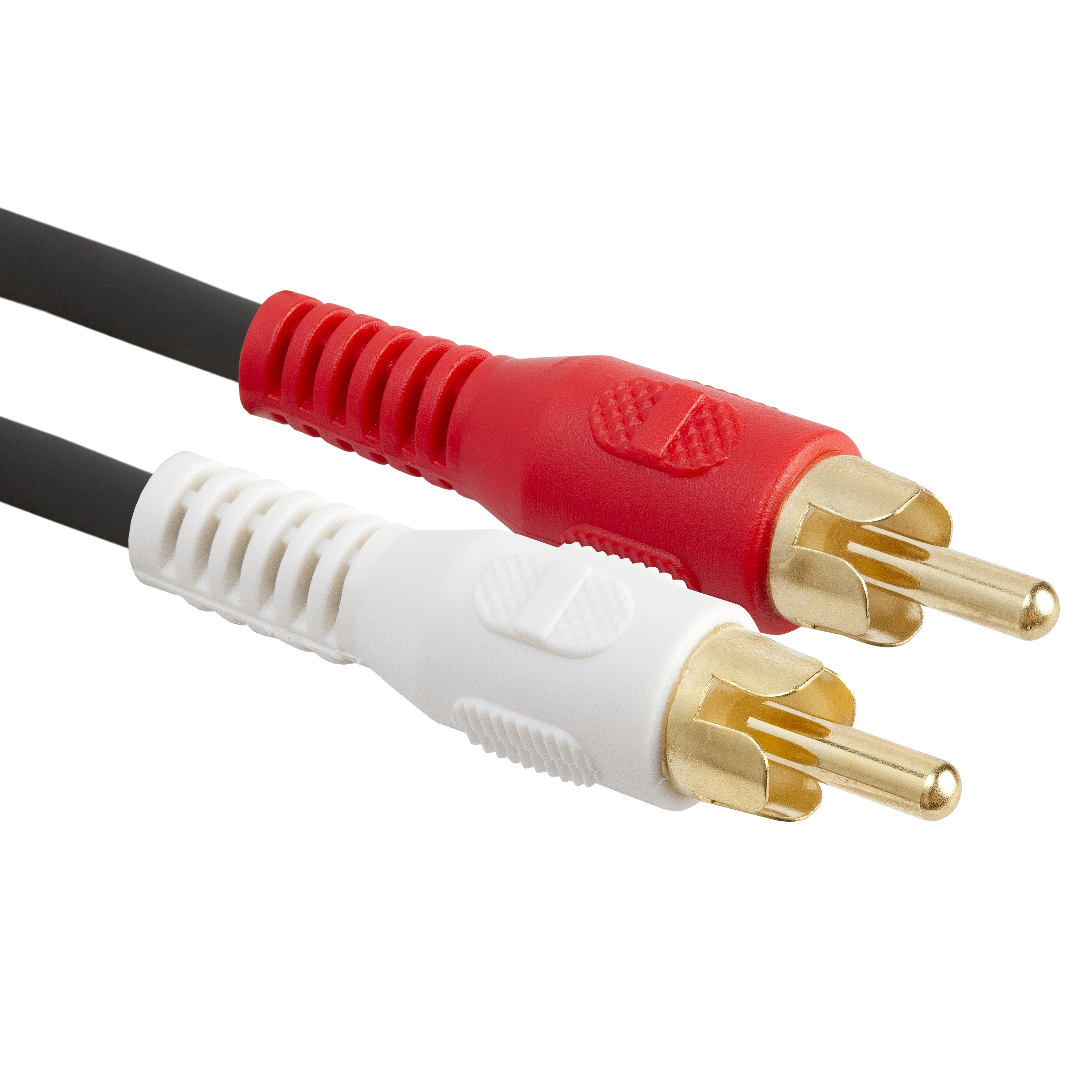
Most commonly used to connect DJ players to mixers, the RCA cable carries the left and right channels at line-level along two separate cables. White is left and red is right, and the signals carried by RCA are unbalanced.
RCA is easy to accidentally unplug, and sometimes has connection issues - particularly if you’re using cheap plugs. Cheap RCA connectors with ‘flower’-shaped ends (see the four ‘petals’ around the central pin in the image above) are bad, as they can be bent out of shape easily, resulting in a loose connection. Connectors with outer rings that fully surround the centre pin are a better pick if you have the choice.
S/PDIF (Digital RCA)
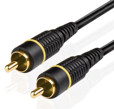
The digital connectors on CDJs and/or mixers use a protocol called S/PDIF to transmit digital audio through RCA cables. If your mixer and CDJs both support it, it’s generally preferable as it minimises the number of conversions between analogue and digital that take place between your USB stick and the master output.
In all physical aspects, digital RCA is identical to analogue RCA, so the cables are fully interchangeable.
XLR
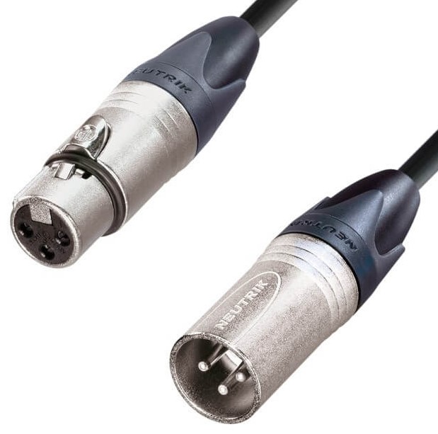
XLR cables are the industry standard way of moving audio around, for good reason. XLR commonly carries both mic and line-level audio, and is balanced thanks to the presence of a third pin (more on that later). It also has locking connectors, meaning you can’t yank it out without pushing a button on the input side - though the mic inputs on the back of DJ mixers often don’t feature a lock.
It also has different connectors on each end, which means multiple XLRs can be daisy-chained to produce a single longer cable. The upper ‘female’ connector with the button plugs into outputs, and the lower ‘male’ connector plugs into inputs.
XLR cables are expensive, but good quality cables are worth it for their reliability. Bad quality connectors typically feel light or hollow in the hand, whereas good quality connectors feel more solid and are made with tougher materials. The above connectors are the good kind - the XLR standard was designed by Neutrik and their plugs are still generally thought to be the best.
6.35mm (1/4”)
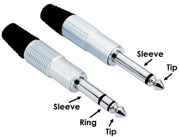
Otherwise known as ‘big jacks’, or just ‘jacks’, quarter-inch cables come in two varieties - TRS on the left, and TS on the right. The difference between the two is simply that TRS has one more pin - this is usually used either to send stereo signals, or to send balanced audio like with XLR’s third pin.
TRS connectors are generally preferable wherever possible, as balanced audio is less susceptible to interference. However, TS is also commonly used, particularly for guitars, guitar pedals and production gear. If a 1/4” connection doesn’t clearly state that it’s balanced, it’s more likely to be unbalanced (but if in doubt the product manual will usually make clear which it is).
In DJ situations, TRS cables are most commonly used for connecting the mixer to the booth monitor speaker, but they can also be used for connecting mics or as master outputs on some mixers. Both of these scenarios usually use balanced audio, so TRS cables are definitely preferable.
The only exception is the send/return loops on mixers, which are typically unbalanced. If you’re fancy enough to be using the send-return loop, you probably don’t need TRS, but it may be worth checking the manual for your effect unit and/or mixer.
Plugging TRS into a TS socket (or vice versa) won’t break anything, particularly if the TRS is being used for balanced - it’s pretty idiot proof. However, if you do happen to be using TRS for stereo instead of balanced audio, you may lose the right channel - in most electronic music this isn’t the end of the world, but it’s probably preferable to sum left and right to mono if you can. Bear in mind that most DJ mixers offer the option to output in mono - either through a switch on the front, or in a configuration menu.
In terms of quality, similar rules apply to XLR.
Speaker-level 6.35mm
Note that TS 1/4” cables are commonly also used for connections from amplifier to speaker, particularly on very cheap passive systems. You should not use regular, line-level TS cables for this, as a speaker level signal requires the cable to transmit more power than a typical line-level cable is designed for.
If in doubt, look at the writing on the cable - if it says ‘microphone cable’ or ‘instrument cable’ then it’s not appropriate for high-power signals. If it mentions ‘speaker cable’ then it should be fine. A speaker cable will be noticeably thicker and heavier than a line-level cable.
speakON
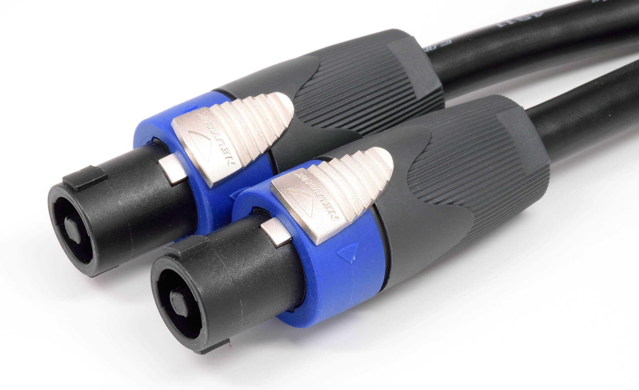
Much like XLR, speakON is a type of cable designed by Neutrik specifically for live scenarios. It’s built to carry speaker-level signals, but is much better suited to the job than jack cables. It has locking connectors, meaning it can’t be yanked out accidentally, can carry more power and is generally more reliable.
Plugging in or unplugging a speakON cable for the first time can be a confusing experience, so bear in mind that you have to line up the (differently-sized) protrusions on the connectors, insert it, then twist it. The lock should have clicked into place. To unplug, just find and pull back the lock on the male connector and reverse the steps.
Advanced sound tech
Phono signals and RIAA equalisation
Vinyl records come with a few specific challenges for mastering engineers and listeners. There are two that are particularly interesting here: firstly, the needle can easily skip, particularly when playing back loud bass frequencies. Secondly, louder low ends require more physical space on the disc. Finally, records famously have a certain level of hiss and crackle when playing back, which tend to occupy the higher frequencies.
A technique called RIAA equalisation neatly solves both of these problems. Essentially, before it is cut into the record surface, a track is equalised in much the same way you’re used to on DJ mixers. The high frequencies are boosted, and the low frequencies are cut. Then, when the record is played back, the highs are cut and the lows are boosted to compensate. This is done with a standardised EQ curve defined by the Recording Industry Association of America in the 1950s.
The benefits here are two-fold: by reducing the level of the bass on the record, we reduce the space needed and the likelihood of skipping. Separately, boosting the high-end means that the high frequencies in the actual recorded music have an advantage against the high frequencies created by hissing and crackling as the needle travels through the groove.
The important thing to note here is that a signal coming from a turntable needs equalising before it will sound correct. This is a built-in feature of pretty much all phono preamps, so you shouldn’t need to worry about it, but certainly always make sure you’re connecting turntables to inputs that expect phono signals - failure to do this will result in a thin-sounding signal.
Balanced audio
In order to transmit an electrical signal, we need two metal connections. One way of understanding this fact is that, given we’re building an electrical circuit, the signal needs to flow ‘through’ the device on the receiving end. If there was only one connection, the electrons wouldn’t have anywhere to go. This is true, obviously, but an analogy that makes life a bit simpler when talking about audio signals is to think of each connection as transmitting a certain voltage level.
Under this simplification, the reason we need two ‘poles’ to transmit a signal is because, as well as the actual voltage of the signal, we also need a ‘reference’ level so we have something to compare to, also known as the ‘neutral’. The property that decides how far the speaker moves is the difference between the two voltages. We can call the reference level 0V, and the actual signal might oscillate between +3V and -3V, for example.
Here’s the above signal again, with the neutral voltage added in in green:
So, let’s imagine that we’re sending audio down a cable in the way described above. All is going well, until something near the cable causes some interference (represented in orange):
Interference is a common problem, particularly with weak signals such as those from mics. It can be caused by a whole range of devices and effects, and one cable could even induce voltage into another if run close to it for some distance. This interference will be audible in the reproduced sound, and probably won’t be very enjoyable for an audience to experience.
We have no way of stopping this under the current setup. But balanced audio gives us a solution. We add a second signal, and we flip it. Now, if we get interference, it affects both signals equally:
This may not seem that useful, but the clever bit is what happens at the receiving end of the signal.
The device receiving the signal flips the second signal back over again, giving us two signals:
It then adds the two signals together…
cancelling the interference out entirely:
So, essentially, balanced audio adds a second signal (and therefore a third pole to the cable) and makes the signal travelling through that cable much more resilient to interference.
Building your own cables
One of the huge benefits of pro audio cables is that they can be disassembled and re-soldered with relative ease. If you’re skilled at soldering, or interested in giving it a go, it’s usually cheaper to buy cable and connectors separately and construct your cables yourself. It also gives you the skills to repair almost all audio cable faults yourself, and is very rewarding.
Most cables designed for pro audio (XLR, TRS, SpeakON, etc) can be disassembled in this way - usually by unscrewing the metal or plastic ‘boot’ at the rear of the connector.